What Is a Wind Turbine System and How Does It Work?
A Wind Turbine System converts moving air into electricity through several connected components. Blades capture the wind and turn a rotor; a shaft transfers that rotation to a generator, directly or through a gearbox. Sensors and control systems adjust blade angles and turbine direction as conditions change. Inside the nacelle, cables carry generated electricity down the tower to power-conversion equipment and, often, a transformer. The details matter: even a small change in wind speed can affect output substantially. It is not magic. It is carefully engineered machinery working with a variable resource.
The scale is growing quickly. The Global Wind Energy Council’s Global Wind Report 2025 records 117 gigawatts of new wind capacity installed worldwide in 2024, bringing cumulative capacity to about 1,136 gigawatts. Those figures describe installed capacity, not electricity produced every hour; wind availability and grid conditions shape actual output. German physicist Albert Betz’s theoretical limit is often summarized this way: “No rotor can capture more than 16/27 of the wind’s kinetic power.” That limit helps explain why turbines cannot convert every gust into electricity. A well-designed Wind Turbine System therefore balances aerodynamics, electrical controls, structural strength, and safe operation. Its performance also depends on maintenance, site conditions, and connection to the grid. A turbine may look simple from a distance. Up close, it is a coordinated system—and its real-world performance deserves careful scrutiny.
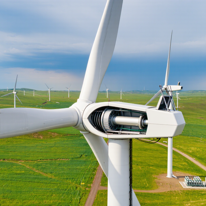
Table of Contents [Hide]
Wind Turbine System Components and Typical 2–6 MW Onshore Ratings
An onshore wind turbine turns moving air into electricity through a coordinated set of mechanical and electrical components. The rotor blades capture wind energy and spin a hub connected to the drivetrain. Inside the nacelle, a gearbox may increase rotational speed before it reaches the generator; some designs use direct-drive generators instead. A converter helps manage electrical output, while a transformer raises voltage for connection to the site’s collection network. The tower supports the rotor and nacelle, and its foundation transfers heavy loads into the ground. Small details matter.
Many onshore turbines are rated between 2 and 6 megawatts. This is the machine’s maximum rated output under specified conditions, not its constant production. Actual generation changes with wind speed, air density, maintenance, and operating limits. At a windy site, the blades may turn steadily; during a lull, output can fall sharply. That distinction matters when estimating annual energy.
Control systems adjust blade pitch and turbine direction to respond to changing wind. Sensors also track vibration, temperature, and other operating conditions, helping crews plan inspections. A simplified diagram makes the system look tidy. Field performance is less tidy: terrain, access for maintenance, and grid connection can all affect results, so a rating alone never tells the whole story.
| Component or system | What it does | Typical characteristics for 2–6 MW onshore turbines | How it works with the rest of the system |
|---|---|---|---|
| Rotor and blades | Capture wind energy and convert it into rotating mechanical energy. | Usually three blades; rotor diameter is commonly about 100–170 m. Blade length is roughly half the rotor diameter. | Wind creates lift on the blades, turning the rotor. The swept area for this diameter range is approximately 7,900–22,700 m². |
| Pitch system | Turns each blade around its longitudinal axis to regulate aerodynamic force. | Typically uses electrically or hydraulically actuated blade bearings and drives. | Adjusts blade angle to control rotor speed and power, and feathers the blades when the turbine shuts down or encounters unsafe conditions. |
| Hub and main shaft | Connect the blades to the drivetrain and transmit rotor torque. | Large structural components designed for substantial cyclic and variable loads. | The hub collects torque from the blades; the main shaft carries it toward the gearbox or direct-drive generator. |
| Gearbox or direct-drive drivetrain | Transfers mechanical power from the slowly rotating rotor to the generator. | Some turbines use a gearbox to increase rotational speed; others use a direct-drive arrangement without a main gearbox. | Both designs deliver rotor power to a generator. The choice depends on turbine design and affects drivetrain layout and maintenance requirements. |
| Generator | Converts mechanical rotation into electrical power. | Rated electrical output is typically within the turbine’s 2–6 MW class. Generator designs and operating speeds vary. | Electricity from the generator is conditioned by the turbine’s electrical conversion equipment before being supplied to the grid connection. |
| Power converter and controls | Manage generator operation and help provide grid-compatible electrical output. | Converter arrangements vary; some process a portion of generator power and others process the full output. | Control systems coordinate generator torque, blade pitch, yaw, and electrical output in response to operating conditions and grid requirements. |
| Transformer and switchgear | Raise voltage and provide electrical isolation, switching, and protection. | Generator-side voltage is commonly in the low-voltage range, often around 690 V; collection-system voltage is commonly about 33–66 kV. | A transformer steps up the turbine’s electrical output for connection to the wind farm’s medium-voltage collection network. Exact voltages depend on the project. |
| Nacelle | Houses and protects major equipment at the top of the tower. | Typically contains the generator and, where fitted, the gearbox, brakes, cooling equipment, and control systems. | The nacelle is turned by the yaw system so the rotor faces the wind. Its equipment arrangement differs between turbine models. |
| Yaw system and wind sensors | Align the rotor with the wind and measure wind conditions. | Yaw drives rotate the nacelle around the tower axis; anemometers and wind-direction sensors commonly provide operating data. | The controller uses sensor measurements to help orient the rotor and manage turbine operation as wind direction changes. |
| Tower and foundation | Support the rotor and nacelle above the ground and transfer loads into the site. | Hub heights are commonly around 80–140 m. Towers are often tubular steel or hybrid structures; foundations are designed for local ground conditions. | Greater hub height can access different wind conditions. Tower and foundation dimensions depend on turbine loads, soil, and site design. |
| Operating wind speeds | Describe the wind conditions under which a turbine typically starts, reaches rated output, and stops. | Typical cut-in speed: about 3–4 m/s; rated wind speed: about 11–13 m/s; cut-out speed: often about 20–25 m/s. | Below cut-in, the turbine generally produces little or no power. It regulates output around its rated capacity and shuts down above its design cut-out conditions. |
| Wind farm collection and grid connection | Combine electricity from multiple turbines and deliver it to the wider grid. | Inter-turbine cables commonly operate at medium voltage; a project substation may raise voltage further for transmission or distribution connection. | Power flows from each turbine through the collection network to the substation, where protection, metering, and voltage transformation support grid delivery. |
| Typical rated capacity | Indicates the turbine’s maximum continuous electrical output under specified operating conditions. | Approximately 2–6 MW per turbine for the onshore rating range covered here. | Rated capacity is not constant annual production. Actual energy generation depends on wind conditions, turbine availability, controls, and site constraints. |
Customers




Smart Robotics brand movie
Watch video