When manufacturers evaluate forming equipment, the choice often begins with material behavior, not machine appearance. Copper conducts heat and electricity well, yet its softness creates demanding stamping conditions. A Copper Stamping Machine must control feeding, pressure, alignment, and die clearance consistently. In a working factory, these details appear as burrs, scratches, bent terminals, or unstable dimensions. The right equipment reduces such problems while supporting repeatable production.
Experienced operators inspect strip condition before adjusting press settings. They check thickness, temper, surface cleanliness, and coil tension. A precise feeder keeps copper moving steadily through the die. A rigid frame helps maintain alignment during repeated strokes. Proper lubrication and scheduled die inspection also matter. Small errors become expensive at high production volumes. However, no machine solves every process issue. Tool design, material variation, and operator training remain important. This is where practical judgment matters.
Technical specifications should be compared with actual production needs. Review rated tonnage, stroke rate, working width, automation options, safety systems, and service support. Ask suppliers for measurable data, maintenance guidance, and application references. A trial using your copper grade can reveal feeding marks or springback. That evidence is more useful than a polished brochure. Reliability is built through testing and disciplined maintenance. Even experienced teams can overlook heat, vibration, or gradual die wear. A careful review leaves room for correction. Choosing a Copper Stamping Machine is therefore a process decision, not merely a purchase. It should balance quality, productivity, energy use, and long-term support. The best choice is the one that performs consistently on your line.
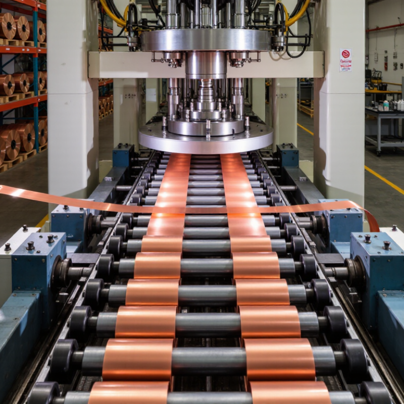
A copper stamping machine is industrial equipment that shapes copper sheet or strip under controlled pressure. It uses a press, a matched die, and a feeding system. The die determines the final profile, while the press supplies repeatable force. Depending on the tooling, the machine can perform blanking, punching, bending, or shallow forming.
Copper is soft, conductive, and highly workable, but it can still deform unexpectedly. Experienced operators check material thickness, hardness, grain direction, and die clearance before production. These details affect burrs, cracks, springback, and dimensional accuracy. A well-adjusted machine can produce terminals, connectors, shields, and other electrical components with consistent edges. Small defects matter.
In a practical workshop, operators monitor feed alignment and press noise during each run. Unusual vibration may indicate worn tooling or poor setup. Regular inspections should include die surfaces, lubrication points, guards, and emergency controls. Measurement tools then verify hole position, bend angle, and overall width. Automation improves output, but it does not replace judgment. The process is not flawless. Copper residue, tool wear, and changing coil tension can still create variation. Careful records and timely adjustments make the machine more dependable.
Copper stamping begins with a coil or sheet entering a guided die. Rollers feed the material at a controlled length. A press then applies force through a punch, shaping or cutting the copper in milliseconds. The die clearance must match the copper grade and thickness. Poor clearance can create burrs, cracks, or uneven edges. Small details matter.
According to the U.S. Geological Survey’s Mineral Commodity Summaries 2024, global copper mine production reached approximately 22 million metric tons in 2023. The International Copper Study Group’s 2024 market forecast also expected refined copper demand to keep growing in 2025. These figures support continued demand for accurate, high-volume forming. Copper’s excellent conductivity makes stamped parts useful in electrical connectors, terminals, and heat-transfer components. However, the process is not magically repeatable. Tool wear, springback, and inconsistent lubrication can slowly change results. A perfect first run is uncommon.
Tips: Measure strip thickness before setup. Confirm feed length with a sample piece. Use suitable lubrication without contaminating contact surfaces. Inspect burr height and hole position during production, not only at the end. Record press force and reject patterns. This practical data helps technicians correct problems earlier, although even experienced teams can overlook gradual die wear.
Copper stamping offers a practical balance of electrical performance, production speed, and dimensional consistency. Copper conducts electricity efficiently, making it suitable for terminals, busbars, connectors, and heat-transfer components. A well-maintained stamping machine can produce hundreds of matching parts with limited manual handling. It also supports thin sheets and detailed shapes, which can reduce material waste and assembly time. The results depend on tooling accuracy, though. Poor clearance may create burrs, distortion, or uneven edges.
Tips: Check copper thickness before production. Match the die clearance to the material. Keep the tooling clean and properly lubricated. Inspect the first pieces with calipers or a measuring gauge. Small errors can multiply quickly in large batches. Ventilation and safe machine guarding also deserve attention.
Copper stamping can lower unit costs when production volumes are steady. It may also improve connection reliability because stamped surfaces remain consistent. However, copper is softer than many alloys, so tool wear and surface marks require regular inspection. From practical shop-floor experience, rushing setup often causes more waste than slow production. That is an easy lesson to overlook. Engineers should review conductivity, hardness, bend direction, and required tolerances before selecting a process. A simple prototype run can expose weaknesses that drawings sometimes hide.
Copper stamping combines high electrical and thermal conductivity with fast, repeatable production. The following figures represent typical engineering ranges and material properties; actual results depend on copper alloy, part geometry, tooling, press capacity, and process settings.
| Evaluation Dimension | Typical Copper Stamping Data | Why It Matters | Common Alternative or Reference | Practical Advantage |
|---|---|---|---|---|
| Electrical conductivity | Approximately 97–102% IACS for high-conductivity copper grades | Allows efficient current transfer and helps reduce resistive power loss in conductive components. | Commercially pure aluminum is approximately 61% IACS; stainless steel is commonly below 5% IACS. | Excellent conductivity |
| Thermal conductivity | Approximately 380–400 W/m·K for high-conductivity copper | Transfers heat rapidly away from electrical contacts, terminals, heat spreaders, and busbars. | Aluminum is typically around 200–235 W/m·K, while many stainless steels are near 15 W/m·K. | Faster heat dissipation |
| Production speed | Typical mechanical press operation: approximately 60–600 strokes per minute, depending on the part and die | Progressive and high-speed stamping can produce large quantities with consistent cycle times. | Machining generally requires separate cutting paths and longer cycle times for thin, repeated parts. | High throughput |
| Material thickness range | Common strip and sheet applications: approximately 0.10–3.00 mm | Supports miniature electronic contacts as well as heavier terminals, brackets, shields, and busbar components. | Available thickness depends on alloy temper, press tonnage, die clearance, and required feature detail. | Flexible part design |
| Dimensional repeatability | Typical stamped features may achieve approximately ±0.05–±0.25 mm under controlled conditions | Repeatable dimensions help maintain reliable assembly fit and stable electrical contact performance. | Final tolerance depends on material temper, tooling accuracy, springback, burr control, and inspection method. | Consistent quality |
| Material utilization | Approximately 70–95% in many optimized strip-stamping layouts | Strip nesting and progressive tooling can reduce scrap compared with processes that remove large volumes of material. | Actual utilization varies with blank shape, pitch, carrier design, edge margin, and recycling practices. | Lower material waste |
| Part complexity | One progressive die can combine blanking, piercing, bending, coining, and forming operations | Multiple features can be produced in a single automated sequence, reducing manual handling and secondary operations. | Separate machining, bending, or assembly steps may be required for comparable multi-feature parts. | Integrated processing |
| Surface and edge quality | Clean shear zones are achievable with suitable clearance, sharp tooling, and controlled lubrication | Good tooling practice helps reduce burrs, deformation, and contact-surface defects. | Fineblanking or secondary deburring may be needed when exceptionally smooth edges are specified. | Reduced finishing |
| Suitable applications | Electrical terminals, busbars, connectors, shielding parts, clips, heat spreaders, and precision brackets | These applications benefit from copper’s conductivity, ductility, formability, and heat-transfer capability. | Material selection should also consider strength, corrosion exposure, operating temperature, and contact requirements. | Broad application range |
| Automation potential | High; coil feeding, in-die sensing, automatic inspection, and part collection can be integrated | Automation improves production continuity, traceability, labor efficiency, and process consistency. | Automation level depends on tooling design, part geometry, quality requirements, and production volume. | Scalable production |
| Economic suitability | Most advantageous for medium- to high-volume production after tooling costs are amortized | Per-part cost can decrease substantially as production volume increases and setup time is spread across more parts. | Laser cutting, machining, or manual forming may be more economical for prototypes and very small batches. | Lower unit cost at scale |
Copper stamping machines serve several demanding industries because copper combines high conductivity with strong formability. Electrical and electronics manufacturers use them for busbars, terminals, connectors, contact clips, and shielding parts. The U.S. Geological Survey’s Mineral Commodity Summaries identifies electrical products, building construction, transportation equipment, and industrial machinery as major copper end-use sectors.
Automotive production is expanding this demand. The International Energy Agency’s Global EV Outlook 2024 reported almost 14 million electric car sales in 2023. These vehicles require copper-rich busbars, battery connections, charging components, and compact power-control parts. Stamping supports repeatable dimensions and high-volume production, especially when thin copper sheet must be shaped without excessive material waste. Small parts matter.
Heating, ventilation, air-conditioning, appliance, and renewable-energy manufacturers also use copper stampings. HVAC systems need formed terminals and electrical interfaces near motors and compressors. Solar inverters and energy-storage equipment require conductive connection parts. In practice, engineers must balance conductivity, springback, burr control, and tool wear. A faster press is not always better. Poor clearance can damage edges and increase rejection rates. This is where production experience matters, because material thickness, temper, and geometry can change the result. Industry reports show broad demand, but each application still needs testing rather than assumptions.
Copper stamping machines are widely used to produce terminals, connectors, busbars, clips, shielding parts, and other precision components. The chart shows estimated U.S. copper consumption by end-use sector, highlighting the industries with strong demand for stamped copper components. Data source: U.S. Geological Survey, Copper Mineral Commodity Summary, 2024.
Building construction and electrical/electronic products are major application areas because they require high volumes of conductive, corrosion-resistant, and precisely formed copper parts.
Selecting the right copper stamping machine begins with the material, not the advertised speed. Record the copper grade, sheet thickness, coil width, and required part shape. Soft copper may deform around sharp corners, while harder grades can demand greater forming force. Measure twice.
Calculate the required tonnage from the blanking perimeter, material thickness, shear strength, and forming operations. Add a sensible safety margin, but avoid excessive capacity. An oversized machine may waste energy and reduce control during delicate work. Check the slide stroke, shut height, bed dimensions, and maximum production rate. These details must match the dies and the intended press line.
Pay close attention to feeding accuracy. Small alignment errors can create burrs, uneven holes, or damaged copper surfaces. A reliable machine should support stable coil feeding, adjustable speed, and clear control settings. Inspect guarding, emergency stops, overload protection, and noise levels before purchase. Safety is not a decorative feature.
Ask for sample trials using your actual copper and tooling. Review edge quality, flatness, repeatability, and scrap rates over several cycles. Maintenance access also matters; crowded lubrication points can slow production. Service documentation, operator training, spare-part availability, and recognized safety compliance improve long-term reliability. In practice, selection is rarely perfect. A lower speed with consistent results may outperform a faster press that needs constant adjustment.
Watch video