Why Use a Concentric Reducer Fitting?

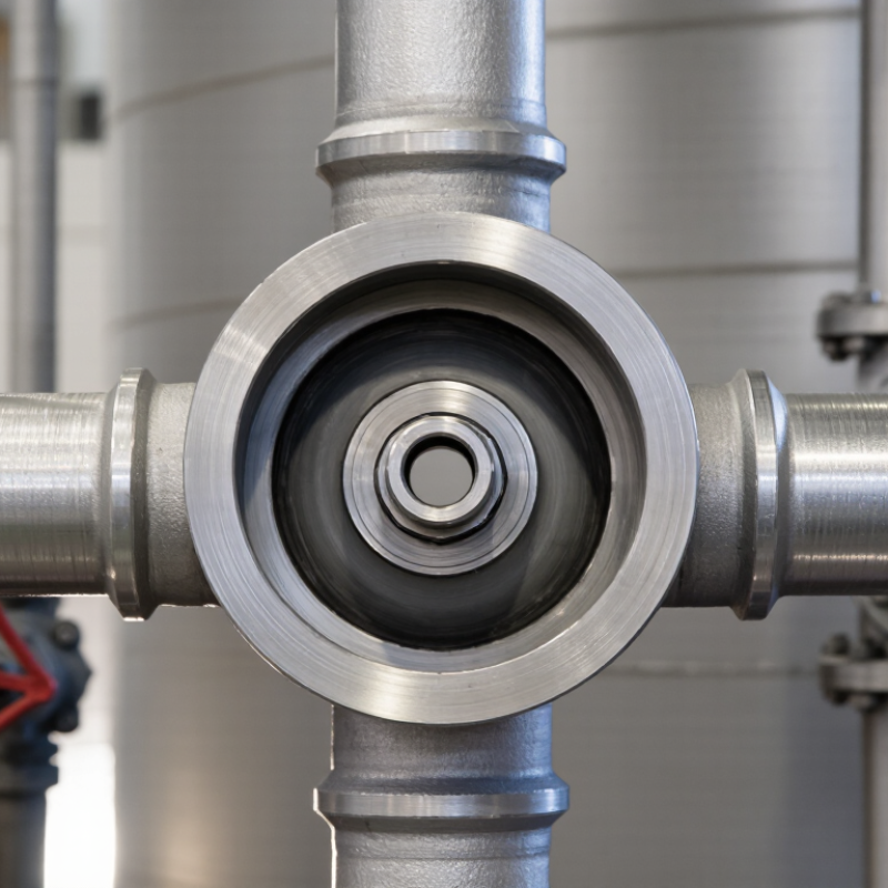
Why use a Concentric Reducer Fitting in a process pipeline? The answer begins with geometry. Its centerlines remain aligned, creating a gradual diameter transition between two pipes. This design can reduce turbulence, simplify support layout, and maintain a cleaner flow path in vertical installations.

Industry data supports careful fitting selection. Grand View Research reports continued growth in the global pipe fittings market, driven by oil and gas, chemicals, water treatment, and industrial construction. The report also highlights rising demand for durable, standardized components. ASME B16.9 establishes dimensional requirements for factory-made wrought butt-welding fittings. However, compliance alone does not guarantee suitable system performance.

Mohinder L. Nayyar, P.E., a respected piping-engineering author, emphasizes that sound piping design must balance safety, reliability, and economy. That principle applies directly to a Concentric Reducer Fitting. A reducer may look simple on a fabrication table. In service, it influences velocity, pressure loss, vibration, and inspection access.

The details are tangible. Imagine a vertical pump discharge line with a smooth, centered transition and properly aligned welds. Fewer abrupt changes can mean fewer flow disturbances. Yet the assumption needs testing. A concentric design is not automatically ideal for every horizontal suction line. Entrapped air, cavitation risk, and installation orientation still require engineering review.

This article examines where concentric reducers perform best, how standards guide selection, and which practical mistakes can undermine their advantages. The fitting is small. Its consequences may not be.
Why Use a Concentric Reducer Fitting?

What Is a Concentric Reducer Fitting?

What Is a Concentric Reducer Fitting?

A concentric reducer fitting connects two pipes with different diameters along one shared centerline. Its cone-shaped body reduces the flow path evenly from the larger opening to the smaller one. This design is common in vertical piping, pump discharge lines, and systems where balanced flow matters.

During installation, the reducer helps maintain a clean, centered pipe arrangement. A properly selected fitting can reduce turbulence, support stable pressure, and simplify alignment. However, it is not suitable for every layout. In horizontal liquid lines, an eccentric reducer may prevent air pockets or unwanted sediment collection more effectively. This detail is easy to overlook.

Tips: Check the pipe outside diameters, pressure rating, temperature range, and connection type before ordering. Inspect the fitting for dents, cracks, or rough internal surfaces. Keep the reducer aligned with nearby valves and supports. Avoid forcing a misaligned joint into place. Small errors can create stress later.

Material choice also matters. Stainless steel can resist corrosion in demanding environments, while carbon steel may suit standard industrial service. Plastic options can work well in selected chemical or low-pressure applications. Always compare the fitting material with the transported fluid and surrounding conditions. Field measurements should guide the final choice, because drawings are sometimes outdated.

Why Use a Concentric Reducer Fitting? - What Is a Concentric Reducer Fitting?

Data Dimension Concentric Reducer Fitting Practical Significance
Definition A pipe fitting used to connect two pipes with different nominal diameters while keeping their centerlines aligned. It provides a compact and direct transition between larger and smaller pipe sections.
Geometry The fitting is symmetrical around one common center axis, and the reducer body generally has a conical profile. The centered flow path is suitable for straight-line piping layouts and axial equipment connections.
Size transition Connects a larger pipe size to a smaller pipe size; the exact dimensions depend on the applicable piping standard and nominal pipe sizes. Allows the designer to match different pipe diameters within one piping system.
Flow direction Can be installed for flow from the larger end to the smaller end or in the reverse direction, subject to system design requirements. The installation direction should be selected according to drainage, pumping, equipment, and process-flow requirements.
Main purpose To reduce or increase the pipe diameter without changing the pipe centerline. Simplifies piping arrangement and supports a controlled change in flow area.
Typical connection types Common configurations include butt-weld, socket-weld, threaded, and flanged connections, depending on the product design and piping specification. The connection type must match the adjoining pipe, valve, flange, and joining method.
Common materials Carbon steel, stainless steel, alloy steel, ductile iron, copper alloys, and thermoplastics are used for different service conditions. Material selection depends on pressure, temperature, corrosion resistance, fluid compatibility, and applicable codes.
Typical applications Process piping, water distribution, HVAC systems, fire-protection piping, industrial utilities, and equipment connections. Useful wherever a centered transition is required between different pipe diameters.
Advantages Compact design, aligned centerline, simple installation concept, and compatibility with many joining methods. Can reduce layout complexity when the connected piping and equipment are on the same axis.
Important limitation The centered transition may not be suitable where an offset flow path, bottom-level drainage, or top-level vapor clearance is required. An eccentric reducer may be more appropriate in systems where fluid accumulation or air pockets must be minimized.
Selection factors Nominal pipe size, pressure class or wall thickness, temperature, material, connection type, corrosion allowance, applicable standards, and installation orientation. Correct selection helps ensure dimensional compatibility, mechanical integrity, and reliable long-term service.

Note: Dimensions, pressure ratings, and tolerances should be verified against the applicable piping standard and project specification before fabrication or installation.

How Does a Concentric Reducer Fitting Work?

Why Use a Concentric Reducer Fitting?

How Does a Concentric Reducer Fitting Work?

A concentric reducer fitting connects larger and smaller pipes along one shared centerline. Its tapered body narrows the flow passage gradually. This transition helps maintain a balanced layout in vertical piping and equipment connections. As the diameter decreases, fluid velocity usually increases. Pressure may also change, depending on flow rate, fluid properties, and system resistance. Engineers check these factors before selecting the fitting size.

During installation, the reducer is aligned with the pipe axis and joined by welding, threading, or another approved connection method. Correct alignment matters. Even a small offset can create stress at the joint. In practical work, technicians inspect the taper, wall thickness, and connection ends before fitting. A concentric design may support smoother flow than an abrupt size change, but it cannot remove turbulence completely. The wrong reducer can still cause vibration, noise, or unwanted pressure loss.

Tips: Confirm the inlet and outlet diameters from current drawings. Measure twice. Keep the fitting centered, especially near pumps, valves, and vertical runs. Follow qualified engineering guidance for material selection, temperature, pressure, and corrosion conditions. A clean-looking installation can still be poorly supported. That detail is easy to overlook.

What Are the Main Uses of Concentric Reducers?

A concentric reducer connects a larger pipe to a smaller pipe while keeping both centerlines aligned. Its main use is to manage diameter changes in compact piping systems. Engineers often install it near pumps, tanks, valves, and process equipment where space is limited. The fitting creates a gradual transition, which can reduce sudden turbulence compared with an abrupt size change.

It is especially useful in vertical pipe runs. For example, a 100-millimeter supply line may reduce to 50 millimeters before entering a control valve. The shared centerline helps maintain a neat layout and supports easier alignment during installation. Concentric reducers are also common in water, air, steam, and selected chemical service lines, provided the material and pressure rating suit the application. Weld preparation matters. Poor alignment can create stress and uneven flow.

Horizontal liquid piping needs more thought. A concentric reducer may trap air near the upper side of the fitting, depending on the layout and flow direction. I have seen drawings accept this detail too quickly. An eccentric reducer can be better in some liquid services, especially where drainage or pump suction conditions matter. The correct choice depends on flow behavior, pipe orientation, pressure loss, maintenance access, and the equipment connection. A clean appearance is helpful, but it should not replace a proper engineering check.

What Benefits Does a Concentric Reducer Provide?

A concentric reducer connects larger and smaller pipes along the same centerline. Its main benefit is a smooth, controlled change in diameter. This design helps reduce sudden turbulence and limits unnecessary pressure losses when properly sized. In pump discharge lines, the centered transition can also support cleaner alignment and a more compact installation.

The fitting is especially useful where space is limited or where piping must remain symmetrical. Its balanced shape distributes flow around the pipe axis. That can reduce vibration risks in some systems. It may also make welding, inspection, and support placement more straightforward. Small detail. Big difference.

In practical installations, engineers still need to check flow direction, velocity, wall thickness, and material compatibility. A concentric reducer is not a magic fitting. In horizontal liquid lines, it may create unwanted air pockets, depending on the arrangement. That assumption can fail. An eccentric reducer may work better in those cases. Correct selection depends on the medium, equipment connection, and pipeline position. Reliable results come from matching the fitting to actual operating conditions, not choosing by appearance alone. Consistent measurements and proper installation remain essential.

Why Use a Concentric Reducer Fitting?

The chart shows the theoretical flow-area retained when reducing between idealized circular pipe inside diameters.

A concentric reducer keeps the inlet and outlet on the same centerline. This symmetrical geometry provides a compact transition, supports straightforward alignment, and is commonly suitable for vertical pipe runs or systems where uniform radial flow distribution is important.

The percentages are calculated using the circular area formula A = πd² / 4. As the inside diameter decreases, the available flow area decreases and fluid velocity may increase when flow rate remains constant. Actual performance depends on pipe dimensions, flow rate, fluid properties, reducer angle, and installation conditions.

How to Select and Install the Right Reducer Fitting

Why Use a Concentric Reducer Fitting?

How to Select and Install the Right Reducer Fitting

A concentric reducer fitting connects pipes with different diameters while keeping their centerlines aligned. This design supports balanced flow in many vertical piping systems. It can also simplify equipment connections where space is limited.

Selection should begin with the pipe sizes, fluid type, operating pressure, and temperature. Check the required material compatibility carefully. Stainless steel, carbon steel, and plastic systems need different fitting specifications. The reducer must also match the pipe schedule and connection method.

Never select by diameter alone.

During installation, inspect the fitting for dents, cracks, and damaged threads. Remove dirt from every joining surface. For welded systems, confirm the bevel, gap, and alignment before tacking. Excessive force can distort the pipe. Install the reducer without creating a visible offset.

Add suitable supports nearby, especially on heavy vertical sections. I once treated support placement as a minor detail. It was not. Unbalanced weight can stress the joint and create future leaks.

Tips:

Confirm flow direction and allowable pressure before installation. Use calibrated tools when tightening threaded connections. Avoid over-tightening. For welded joints, follow the approved procedure and inspect the finished weld. Pressure-test the completed line according to the applicable project standard. Record the fitting material, size, and test results. A small record helps later maintenance, although it is easy to overlook during a busy installation.

Smart Robotics brand movie

Watch video