vacuum coating machines create thin films inside a controlled low-pressure chamber. They are used on products ranging from optical lenses and decorative hardware to electronic components. The machine type matters because each process handles materials, substrates, and production needs differently. A polished finish is not the only measure of success.
Common options include thermal evaporation, electron-beam evaporation, sputtering, and plasma-enhanced chemical vapor deposition. Thermal evaporation can suit relatively straightforward metal coatings. Sputtering offers broader material choices and can produce dense, uniform films, though equipment and process control may be more demanding. Electron-beam systems support materials with higher melting points. Plasma-based methods can deposit useful films at lower substrate temperatures, depending on the recipe. No single method fits every job.
Small differences matter. A curved lens may need even coverage across its surface. A production line may prioritize repeatable cycles and fast loading. A research team may value flexible process settings instead. In equipment evaluations, buyers should compare chamber size, pumping capacity, power supply, fixturing, automation, and service support—not just the advertised coating rate. These details shape real operating costs. They can also be overlooked.
This guide examines the top types of vacuum coating machine and explains where each approach tends to perform well. It also points out practical trade-offs, because a machine that looks ideal on paper may need adjustments for a specific substrate or coating target. Actual results depend on process design and testing. That part takes patience.
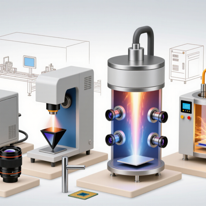
A vacuum coating machine brings several parts together inside a sealed chamber. The chamber limits contact with air while a pumping system lowers the pressure. Gauges track pressure, and valves control the pumping and gas flow. The substrate holder keeps parts positioned near the coating source. Small leaks matter. Even a slight pressure change can affect how particles travel and settle.
Different sources create different coatings. In thermal evaporation, a material is heated until it vaporizes and condenses on the cooler substrate. In sputtering, energetic ions strike a target, releasing atoms that form a thin film on nearby parts. Some processes add a reactive gas to alter the film’s composition. Sensors can track thickness, but their readings may not represent every surface equally. I would not treat a stable pressure reading as proof of a uniform coating; fixture spacing and surface preparation still matter. The chamber may look clean, yet residue can remain in corners.
What Are the Top Types of Vacuum Coating Machines?
Thermal Evaporation and Electron-Beam Coating Systems
Thermal evaporation and electron-beam systems are common choices for depositing thin films in a vacuum. Thermal evaporation heats material in a boat or crucible until it vaporizes and settles on the part. It suits many metals and straightforward coating jobs. The equipment can be relatively simple to operate, but source compatibility and heat-sensitive substrates need careful attention. The setup is simple. Consistent results are not automatic.
Electron-beam systems use a focused beam to heat material inside a crucible. This approach can handle materials with higher melting points and allows precise control of the heating area. However, setup and process tuning may take more effort. A rotating fixture can help coat complex surfaces, though it cannot guarantee uniform coverage in every recess. Small details matter.
Tips: Clean parts thoroughly and check that they are dry before loading. Monitor film thickness with suitable measurement equipment, then inspect representative parts after coating. Keep notes on source power, pressure, and deposition rate. A recipe that worked once may still need adjustment; that part is easy to overlook.
| Coating System | How It Works | Common Materials | Typical Strengths | Considerations | Common Applications |
|---|---|---|---|---|---|
| Thermal evaporation | An electrical current heats a source material in a boat, basket, or crucible until it vaporizes and condenses on the substrate in a vacuum. | Commonly evaporated metals such as aluminum, silver, gold, and copper; some materials require specialized sources or process conditions. | Relatively simple equipment; suitable for many thin metal films; often offers high deposition rates for readily evaporated materials. | High-melting-point or compound materials can be difficult to evaporate without decomposition or composition changes. Line-of-sight geometry can limit coverage on complex shapes. | Decorative metal films, optical layers, electrical contacts, and laboratory-scale thin-film deposition. |
| Electron-beam evaporation | A focused electron beam heats material in a water-cooled hearth or crucible, generating vapor that travels to and condenses on the substrate. | Refractory metals and other high-melting-point materials, including titanium, chromium, and many oxide materials when suitable process controls are used. | Concentrated heating can evaporate materials with higher melting points; multiple hearth pockets can support material changes in some systems. | Equipment is generally more complex than resistance evaporation. X-rays, spitting, and film stress may require process and equipment controls. | Optical coatings, semiconductor research, wear-resistant films, and coatings using high-melting-point materials. |
| Magnetron sputtering | A plasma accelerates ions toward a target; ejected target atoms travel through the chamber and deposit as a film. Magnetic fields help confine electrons near the target. | Metals, alloys, and, with reactive gas or compound targets, materials such as oxides and nitrides. | Good control over film composition and thickness; broadly applicable to conductive materials and reactive coating processes. | Requires a plasma and process-gas control. Deposition conditions, target material, and geometry affect rate, uniformity, and film properties. | Architectural glass, displays, tools, electronics, and functional metal or compound coatings. |
| Ion plating | A vaporized coating material is combined with a plasma; energetic ions bombard the substrate and growing film during deposition. | Metals and compound coatings, including some nitrides and carbides, depending on the source and reactive-gas process. | Ion bombardment can improve film adhesion and density compared with unassisted evaporation in suitable processes. | More process-intensive than basic evaporation; ion energy and substrate heating must be controlled to avoid damage or excess stress. | Wear-resistant tools, components, and decorative or functional coatings that benefit from strong film adhesion. |
Note: Material compatibility, coating quality, and deposition performance depend on the specific equipment, substrate, film design, and process settings.
Sputtering machines eject atoms from a solid target and deposit them onto a substrate inside a vacuum chamber.
The main configurations differ by power source, target shape, and production layout. DC magnetron systems suit conductive targets and steady, high-throughput coating. RF systems can handle insulating materials, but often require slower deposition. Pulsed DC helps manage arcing on reactive coatings. These are practical tendencies, not guarantees; material recipes matter.
Planar magnetrons are common for flat panels and glass, where broad targets coat large surfaces. Rotary cathodes expose more target area during operation, improving material use in continuous production.
Cluster tools connect separate chambers for sequential layers, while inline systems move substrates past coating stations. A practical distinction. Inline layouts support volume; cluster systems offer tighter control over individual steps. Yet added stations mean more maintenance and process coordination.
Demand provides context, not a direct measure of sputtering sales. SEMI reported global semiconductor manufacturing equipment sales of $106.3 billion in 2023, showing the scale of investment in fabrication tools.
The IEA’s Renewables 2024 report recorded nearly 510 GW of renewable capacity additions in 2023, with solar PV accounting for about three-quarters. Both sectors use coated materials, though not every coating step uses sputtering. There is no perfect layout. Engineers still need to test uniformity, target utilization, and film stress on the actual substrate.
Ion-plating machines combine a vacuum chamber, a vapor source, and a plasma that energizes coating material. An electrical bias on the parts helps attract ions to their surfaces. This can improve coating adhesion and produce a dense layer, depending on the material and settings. Operators often adjust pressure, bias voltage, temperature, and deposition time to suit the substrate. Small changes matter.
Vacuum arc deposition machines use an electrical arc to vaporize a solid cathode. The resulting plasma contains highly ionized coating material, which can deposit quickly on prepared parts. A typical system includes arc power supplies, vacuum pumps, substrate fixtures, and process controls. Arc droplets may also reach the surface, leaving tiny raised defects. Filters and careful process tuning can reduce them, but results vary with equipment design and coating conditions.
These machines suit different priorities. Ion plating offers flexible control over ion bombardment, while arc deposition can deliver high ionization and fast coating rates. Neither method guarantees a durable finish by itself. Surface cleaning, part geometry, and temperature limits all affect performance. A recessed feature, for example, may receive less uniform coverage than an exposed edge. Test samples help reveal that gap before a full production run. Even then, measurements need context; a single thickness reading can miss uneven coverage across a complex part.
Choosing a vacuum coating machine starts with the coating material and the part’s final job. Thermal evaporation suits many metals and optical layers, especially when gentle deposition matters. Sputtering handles alloys and ceramic targets well, often producing dense, uniform films. Arc deposition can create hard protective coatings, though droplets may affect surface finish. The choice is rarely neat.
Match the process to the part. A stainless-steel cutting tool needs a different coating and heat profile than a glass lens or plastic component. Check substrate temperature, chamber size, fixture rotation, coating thickness, and production volume. Large or complex parts may need multiple sources and careful fixturing to reduce thin spots. Grand View Research valued the global physical vapor deposition market at about USD 23.5 billion in 2023, and projected 6.5% annual growth from 2024 to 2030. This report signals broad industrial demand, but market growth alone cannot identify the right machine.
Tips: Ask suppliers for coating trials using your actual material and part geometry. Measure thickness at several points, inspect adhesion, and record cycle time. Small test coupons help, but they may not reveal every shadowing problem on a full-size component. A trial can still surprise you.
Watch video