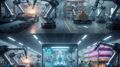
An industrial robotic arm is a programmable machine designed to move materials, tools, or components with controlled precision. It may weld a vehicle frame, place circuit boards, or lift heavy parts repeatedly. Unlike a human worker, it does not become tired in the same way. However, it still depends on careful programming, maintenance, and supervision.
Joseph F. Engelberger, widely recognized as a pioneer of industrial robotics, once said, “I can’t define a robot, but I know one when I see one.” The statement sounds simple, yet it highlights an important issue. A robotic arm is more than metal links and motors. Its controller, sensors, software, end effector, and safety systems work together as one production tool. Servo motors rotate individual joints. Encoders report their positions. The controller compares those signals with programmed movements and corrects the arm continuously.
The process can look effortless. A gripper closes around a part, lifts it, turns it, and places it on a conveyor. Inside that brief motion, complex calculations are happening. The arm must manage speed, reach, payload, and collision risks. Small errors can affect product quality. Sometimes, the advertised precision also depends on ideal factory conditions. Dust, vibration, worn gears, or poor calibration can change performance. This is where practical experience matters. Understanding how an industrial robotic arm works requires examining both its impressive capabilities and its real limitations.
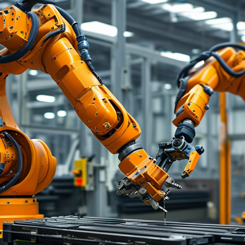
ISO 8373 describes an industrial robot as an automatically controlled, reprogrammable, multipurpose manipulator. It must operate through three or more programmable axes. The robot may be fixed or mobile. Its purpose is industrial automation, such as welding, handling, assembly, or inspection. A controller sends motion commands to motor-driven joints. Encoders report each joint’s position. The system then adjusts movement in real time. It feels mechanical, but the decisions depend on programmed coordinates, speed limits, and safety signals.
Payload means more than the product being moved. It includes the gripper, cables, brackets, and workpiece together. Exceeding the rated payload can reduce repeatability and accelerate joint wear.
Six-axis robots are common because six independent movements can position and orient a tool in three-dimensional space. The first axes usually control reach and rotation. The wrist axes control tool angle.
Six axes are flexible, not automatically better. A simpler robot may be more stable and economical for one repeated path. In practice, technicians sometimes focus on maximum payload and overlook wrist torque. That mistake deserves attention.
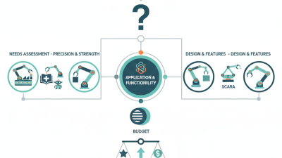
Tips: Measure the complete tool package before selection. Check payload at the farthest reach, not only near the base. Review cycle time, reach, repeatability, and mounting conditions together. Leave a practical margin. Real production is rarely as clean as a simulation.
An industrial robotic arm is a programmable machine that moves materials, tools, or components with controlled precision. Its structure resembles a human arm, but each joint is driven by a motor and monitored by sensors. Links connect the joints, while a controller calculates the end-effector’s position. The International Federation of Robotics reported 541,302 industrial robot installations worldwide in 2023. Its World Robotics 2024 report also recorded about 4.28 million robots operating globally.
Motion & Control
Motion begins with joint coordination. Rotary joints change angles, and linear joints extend or retract along an axis. Forward kinematics converts joint angles into the tool’s position. Inverse kinematics works backward, finding the joint movements needed to reach a target point. The controller repeats this calculation continuously. Small encoder errors can shift the tool several tenths of a millimeter. That is the elegant part.
Precision in Practice
Repeatability is not the same as absolute accuracy. ISO 9283 testing evaluates how closely a robot returns to programmed positions. Submillimeter repeatability is achievable in controlled conditions, especially with stable loads and calibrated tools. Real production cells are less tidy. Heat, vibration, cable drag, payload changes, and worn gearboxes can alter results. The model is never perfect. Technicians therefore verify positions at the actual worksite, not only in simulation. Calibration routines, rigid fixtures, and slower approach speeds often matter more than impressive specifications. Even careful engineers must question a result that looks precise but lacks measurement evidence.
Industrial robotic arms combine mechanical joints with a controlled electrical system. A servo drive converts controller commands into motor movement. It adjusts torque, speed, and position several times each second. An encoder reports the joint’s actual angle back to the controller. This feedback exposes small errors, such as a 0.4-degree overshoot near a fixture. Precision depends on more than motor power. Wiring, calibration, load balance, and temperature also matter.
A programmable logic controller, or PLC, coordinates the arm with sensors, clamps, conveyors, and safety circuits. For example, a photoelectric sensor can confirm a tray’s position before motion begins. The PLC may pause the sequence when a guard switch opens. Motion software then plans a trajectory through taught points. It controls acceleration, blending, and approach speed, rather than simply jumping between coordinates. A smooth curve reduces vibration and protects the payload.
In practical commissioning, engineers watch position traces and test slow cycles first. They compare commanded and measured angles under the real load. A dry run often reveals cable drag or an incorrectly entered tool offset. Small errors become expensive at production speed. Not every fault is obvious. Encoder noise can resemble a mechanical problem, while poor trajectory settings may appear to be a servo failure. Reliable operation requires documented parameters, repeatable tests, and trained maintenance staff. Human review remains essential.
An industrial robotic arm moves through programmed joints, but its real value depends on the end effector. A welding torch, gripper, or dispensing nozzle changes the arm’s practical purpose. The International Federation of Robotics reported 541,302 industrial robots installed worldwide in 2023. That scale shows strong adoption, but installation alone does not guarantee reliable production.
End effectors must match the task, material, and required force. A welding tool needs stable distance, angle, and current control. An assembly gripper may require soft fingers and force feedback. Sensors detect contact, position, temperature, or tool wear. Machine vision adds another layer by locating parts before the arm moves. In 2023, North American companies ordered 31,159 industrial robots, according to the Association for Advancing Automation. More deployments also expose more integration problems.
Calibration matters greatly. A camera can identify a bolt, yet poor lighting may shift its measured position. A force sensor can protect a component, but incorrect thresholds may slow the line. These failures are rarely dramatic at first. They appear as scratches, loose fittings, or repeated pauses. That is where engineering experience becomes useful. Test the complete tool, sensor, software, and workpiece together. A perfect digital model can still fail beside a dusty welding cell. The weak link is often calibration, not the robot. Further review is necessary when operators must frequently correct the system by hand.
The chart presents representative arm-reach ranges commonly used when planning industrial robot cells. Welding applications often require longer reach for access around fixtures, assembly typically uses compact arms for precise part handling, and machine-vision inspection uses a reach that supports camera positioning and coverage of the inspection area. Actual requirements depend on payload, tooling, workspace layout, sensing distance, and safety constraints.
An industrial robotic arm is a programmable machine that moves tools or parts through controlled joints. Electric motors, gear systems, encoders, and software coordinate each movement. A controller compares planned positions with real-time feedback. If a gripper reaches a fixture, accuracy depends on calibration, payload, speed, and the workcell’s physical design.
The scale is substantial: reported figures cite 541,302 industrial robot installations and 4.28 million units in operation worldwide. Those numbers also raise practical safety questions. ISO 10218 addresses robot design, integration, protective measures, and operating requirements. It does not make an entire cell safe automatically. Engineers still need risk assessments, guarded zones, emergency stops, safe operating modes, and validated procedures. A robot can pause correctly while a nearby fixture remains dangerous.
On a factory floor, safety may involve a locked gate, a light curtain, and a clearly marked maintenance position. Operators should understand restart conditions, stored energy, pinch points, and collaborative limits where relevant. Training records and inspection results provide useful evidence of control. In my experience, commissioning often reveals small weaknesses: a sensor faces the wrong angle, or a reset button sits too close to the hazard. These details are easy to overlook. That is why documented testing should challenge normal assumptions, not merely confirm them. Even a well-designed installation requires periodic review when tools, programs, layouts, or production speeds change.
| Data Dimension | Value | What It Means | Reference or Scope |
|---|---|---|---|
| New industrial robot installations | 541,302 units | The number of industrial robots installed worldwide during 2023. An installation refers to a robot newly placed into operational service during the reporting year. | Worldwide industrial-robot statistics for 2023 |
| Industrial robots in operation | Approximately 4.28 million units | The estimated global operational stock of industrial robots at the end of 2023, covering robots installed in manufacturing facilities and still in service. | Worldwide operational-stock statistics for 2023 |
| Primary mechanical structure | Serial-linked joints and links | A robotic arm uses connected rigid links, rotary or linear joints, actuators, gearboxes, position sensors, and a tool interface to move a payload through programmed paths. | General industrial-robot architecture |
| Common degree of freedom | 4 to 6 axes | Four-axis systems are frequently used for high-speed pick-and-place tasks, while six-axis systems can control both the position and orientation of a tool in three-dimensional space. | Typical industrial applications; configurations vary |
| Typical end-of-arm tooling | Grippers, weld guns, dispensers, or process tools | The end effector performs the production task. Tool selection depends on workpiece geometry, mass, surface, process forces, and required accuracy. | Application-dependent equipment category |
| Main motion-control method | Feedback-controlled servo motion | Controllers compare commanded positions with encoder feedback and continuously adjust motor output to coordinate joint movement, speed, acceleration, and stopping. | Standard industrial motion-control principle |
| Typical production tasks | Material handling, welding, assembly, painting, and inspection | Industrial arms are selected when repeatability, reach, speed, payload handling, or operation in hazardous environments is important. | Common manufacturing use cases |
| Safety standard for industrial robots | ISO 10218-1 and ISO 10218-2 | Part 1 addresses safety requirements for the robot itself. Part 2 addresses the integration of the robot into an application, including safeguards, risk reduction, and the overall robotic cell. | International robot-safety standard series |
| Collaborative robot guidance | ISO/TS 15066 | Provides additional guidance for collaborative robot applications, including collaborative operation methods, risk assessment, contact considerations, and force or speed limitations. | Technical specification for collaborative applications |
| Required safety assessment | Application-specific risk assessment | A safe installation must evaluate the robot, tooling, workpieces, fixtures, software, foreseeable misuse, access points, stopping performance, and interaction with people. | Required engineering and integration practice |
| Common protective measures | Fencing, interlocked gates, scanners, light curtains, and safety-rated controls | Safeguards are selected according to the hazards and operating modes of the complete cell. A robot arm should not be treated as safe solely because it has reduced speed or force. | Industrial robotic-cell safeguarding principles |
| Programming workflow | Teach, simulate, validate, and monitor | Operators or engineers define coordinate frames, tool data, waypoints, speeds, sequences, I/O signals, and safety conditions before production release. | Standard robot-application workflow |
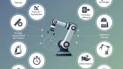
| Performance measures | Reach, payload, repeatability, speed, and cycle time | These parameters determine whether a robotic arm can access the work area, carry the tooling and workpiece, achieve the required positioning consistency, and meet production targets. | Common equipment-selection criteria |
| Operating environment | Defined by application and protection rating | Dust, moisture, heat, chemicals, cleanroom requirements, washdown conditions, and explosive atmospheres may require specialized robot construction and certified cell equipment. | Environmental suitability depends on the complete system |
Note: Global installation and operational-stock figures refer to 2023 worldwide statistics. Safety compliance must be assessed for the complete robot application, not the arm alone.
Watch video